Advanced Techniques
Inset
Edge Loop
Bevel
Collapse
Connect
Edge Ring
4-Sided Polygons
Orthogonal View
Drag Selecting
Dissolve
Rotate
Mirror
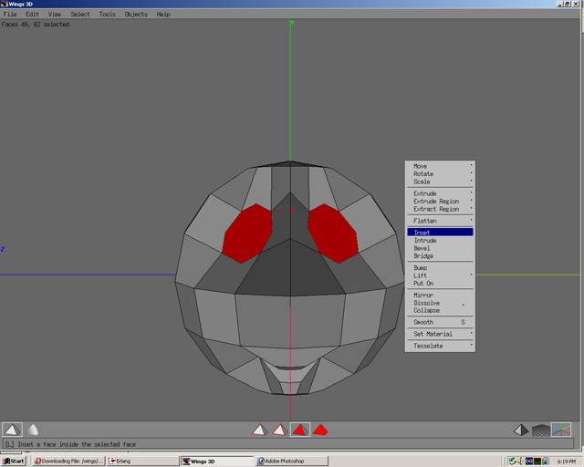
Step 01
Select faces. Right click and select inset.
Step 02
Inset faces to the desired size.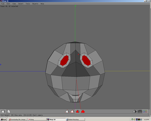
Step 03
Move faces normal.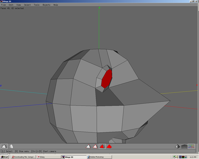
Step 04
Inset faces again.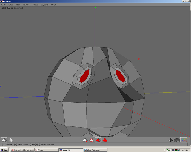
Step 05
Move faces normal.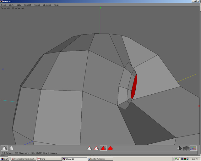
Step 06
Select the two edges.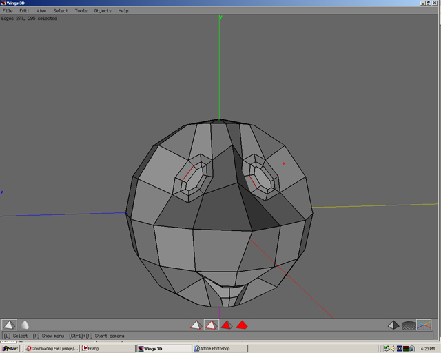
Step 07
Press L to make an edge loop. Notice any edge could have been selected on the edge loop to create an edge loop.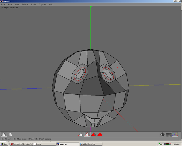
Step 08
The edge loop is created when all the edges meet at one point along the whole ring. Each vertice is at its own “4 way intersection” along the edge loop.
Step 09
With the edge loop still selected. Right click and select bevel.
Step 10
Connect 5 sided polygon areas to make them 4 sided polygon. Right click and select Cut. Select 2.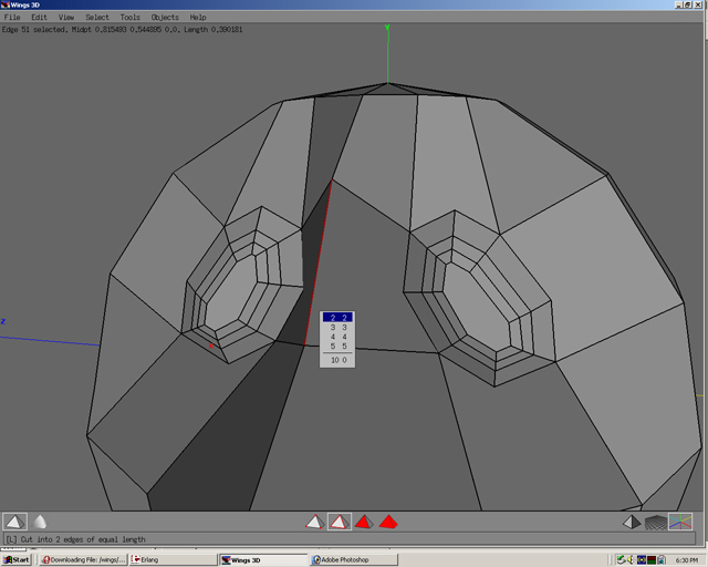
Step 11
Right Click and select Connect or Press C.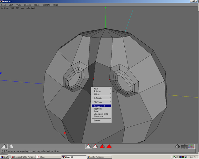
Step 12
Now the 5 sided polygon(or N-Gon) is two 4 sided polygons(or quads)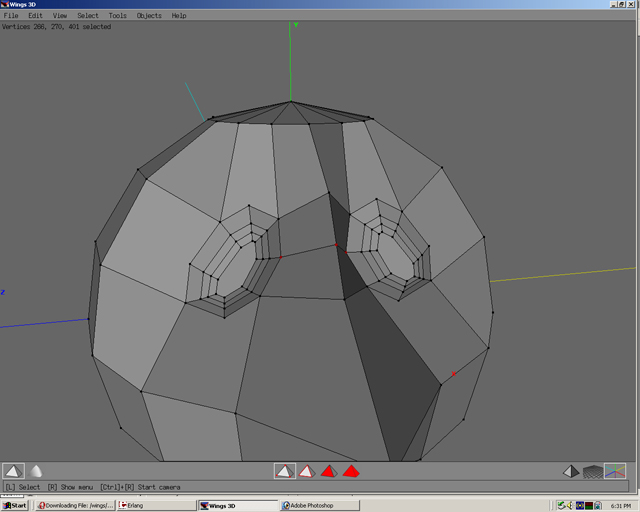
Step 13
Select edge.
Step 14
Select edge ring by pressing G. Notice the edge ring breaks where the 4 side polygons end. It also works with some 3 sided polygons.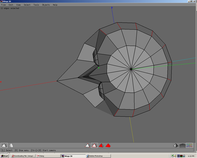
Step 15
Select connect or press C.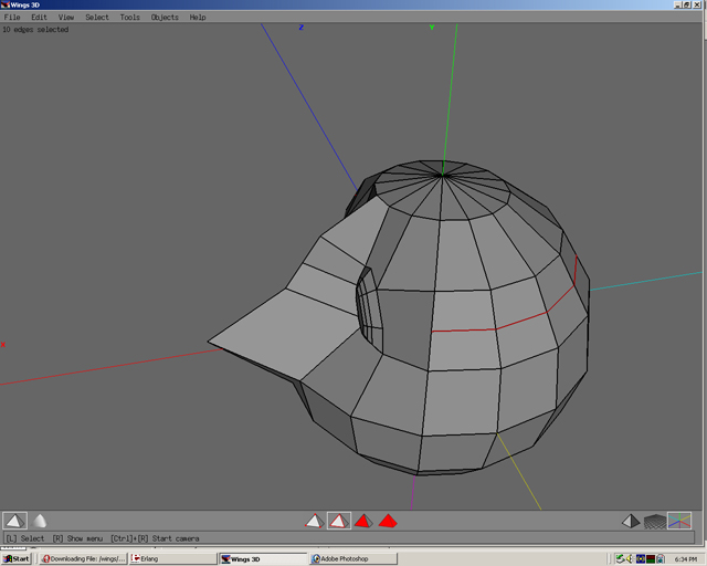
Step 16
Connect vertices to make two 4 sided polygons from a 5 sided polygon.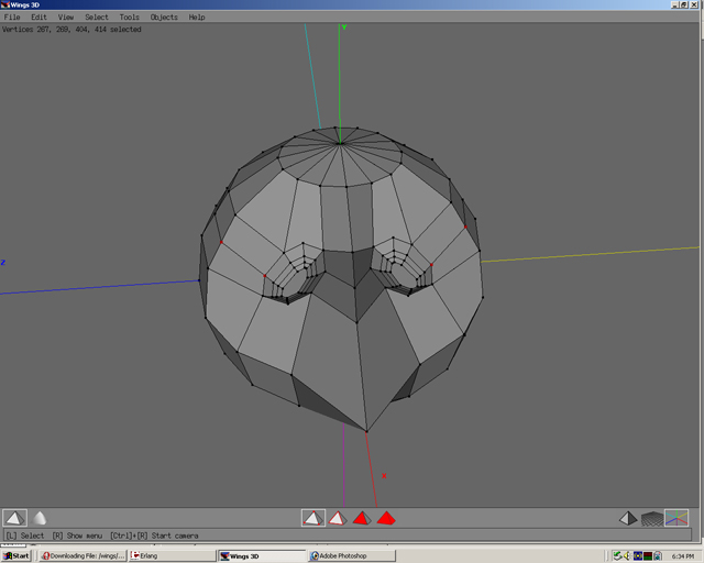
Step 17
The reason to make 4 sided polygons from 5 is for better manipulation when smoothing polygons and also to prevent poles that can make a model look bad.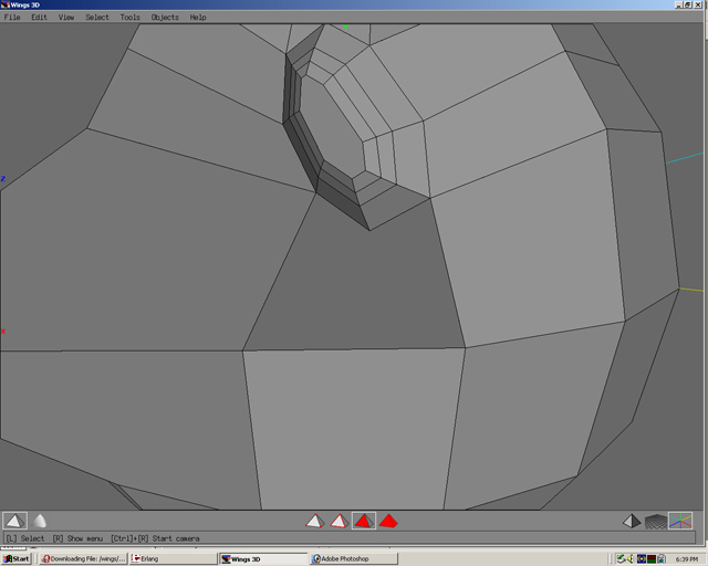
Step 18
Notice the pole made when the model is smoothed.
Step 19
Look at the break in the polygon when the shaded mode(not smooth shaded) is on.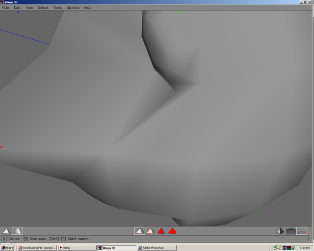
Step 20
Select the two edges and then press G.
Step 21
Connect the two vertices. This makes two 4 sided polygons.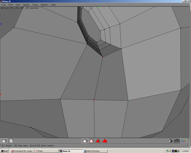
Step 22
Notice the difference in the before and after. 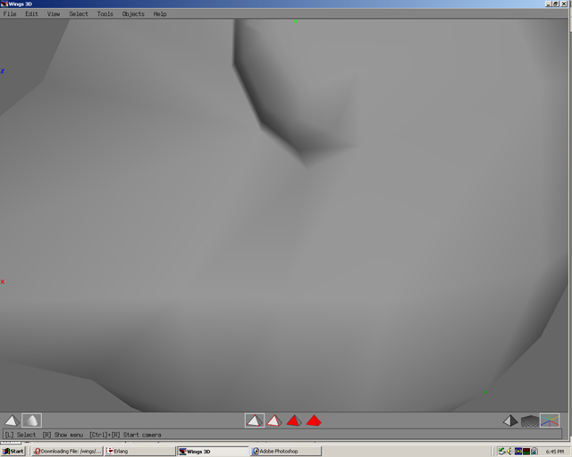
Step 23
Right now you are in a perspective view.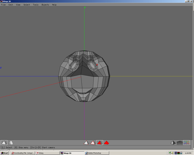
Step 24
To look in orthogonal view press O or the triangle icon in the lower right hand cornder of the screen.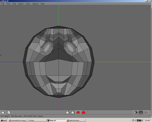
Step 25
Select the faces by first pressing F.Then move the mouse above the model hold the left mouse button and drag. Every face both front and back(not seen) that has was within the drag selection will become selected.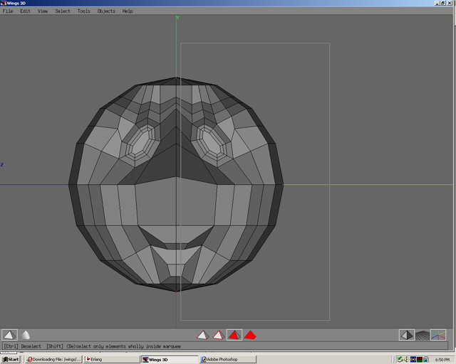
Step 26
Make sure all the faces are selected to make the model be split directly in half. This is why all the facial features were centered on the X axis in the beginning.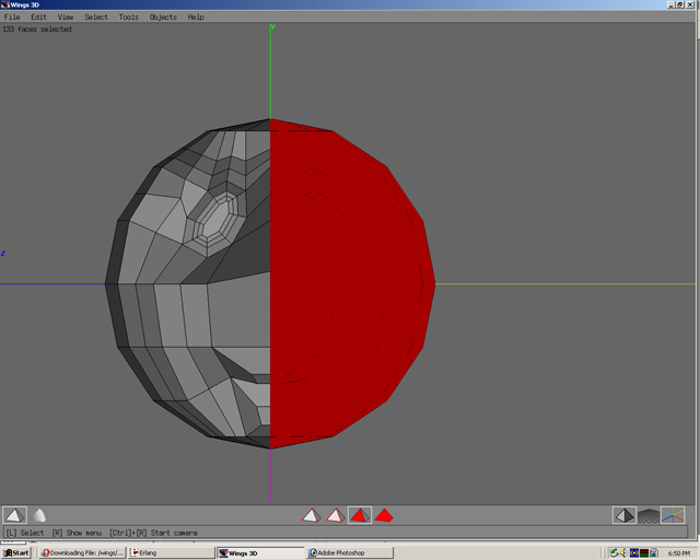
Step 27
Right click and select dissolve.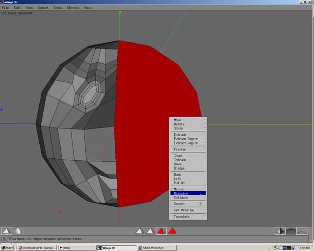
Step 28
Half the face is gone. (It will return).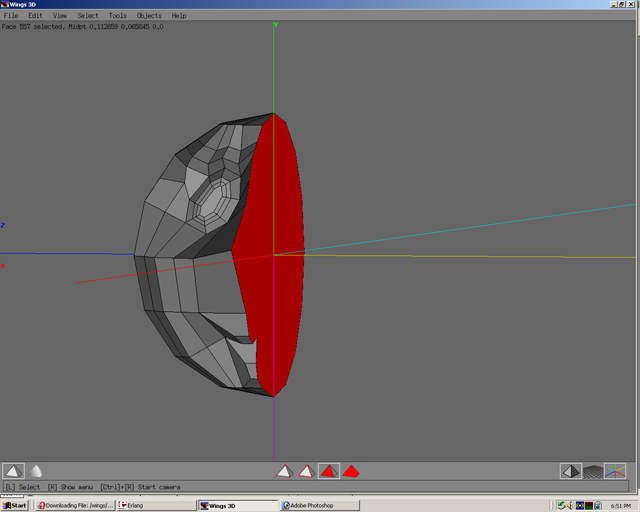
Step 29
Extrude a face from the head.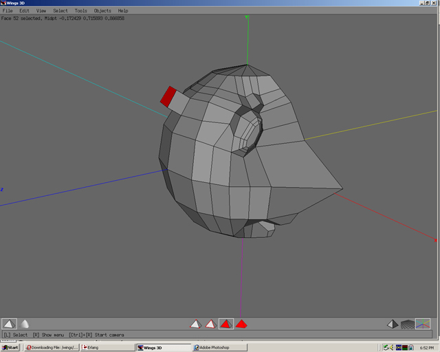
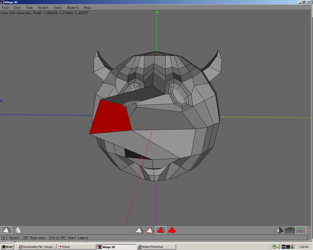
Step 30
Rotate the face on the X axis.
Step 31
Extrude, then scale uniform.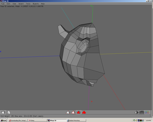
Step 32
Extrude Y.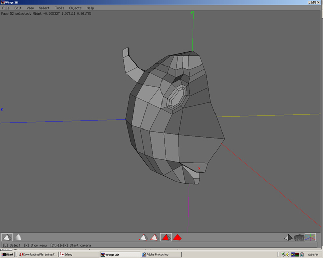
Step 33
With face still selected. Right click and select collapse.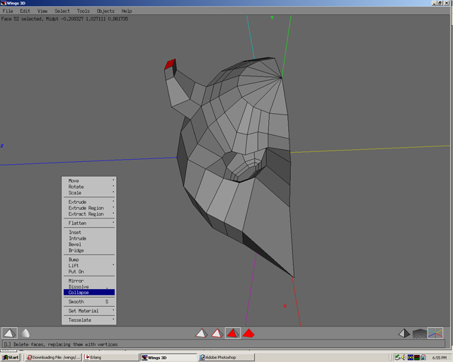
Step 34
Notice the face has collapsed so that each of its 4 vertices now meet at one point.
Step 35
Select face.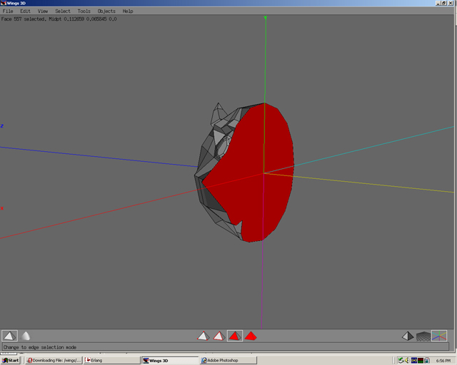
Step 36
Select mirror.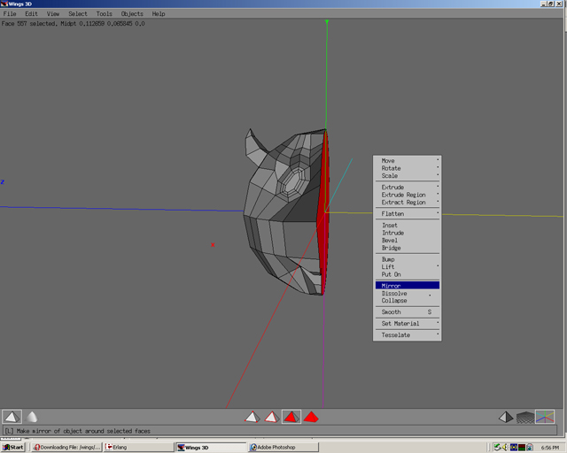
Step 37
Both sides now have the horn. Using the mirror technique can save much time in modelling.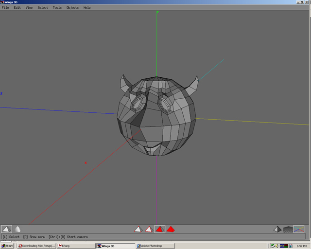
Step 38
Using smooth preview periodically can help to understand how the model would look as a high polygon model or also called a hi-poly model.
Modelling Don'ts
Inside Out
A model is made up of polygons. Select W and the model will be in wireframe mode. The model looks more like a cage or a mesh.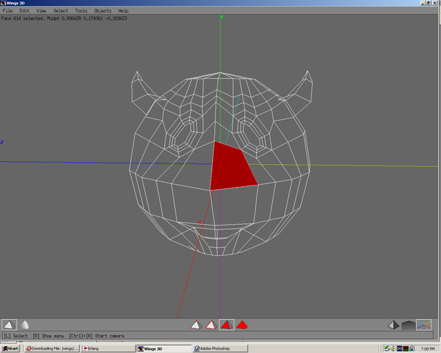
If a face is moved until it pulls the mesh “inside out”, this can make modelling(especially smoothing), mapping, and texturing very difficult.
Multple Primitives
Only use multiple primitives when it is neccessary. Using one primitive and building from that is preferred in most cases.
Click to move on - Intermediate Techniques
Click to move on - Building 3D Body